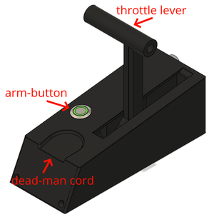
Throttle
The throttle controls the motor and is operated by the pilot during sailing. It controls the duty cycle of the motor via the CAN bus using the standard VESC message format.
Usage
To use the throttle to control the motor the green illuminated arm-button will have to be pressed for a few seconds, however some conditions need to be met to ensure a safe start of the motor.
- The dead-man cord needs to be applied to the bottom of the throttle body, should snap in place magnetically
- The throttle lever Should be in its neutral position, pointing straight up with a noticeable tactile bump
- The CAN bus need to be actively acknowledging packets, which means other devices need to be active on the bus
- No other error should have occurred inside the electronics
If one of these conditions is not met, the throttle will beep the number of times indicated above.
Programming Throttle Position
The throttle position is read out by a magnet attached tot the throttle lever, because the orientation of this magnet is not know in the firmware, this position can be programmed into the EEPROM. To enter programming mode hold down the arm button during power-on. A four beep descending tone should be played, and the LED should do a double blink in red continuously. To program the throttle push lever as far forward as possible and press the button, a single beep be heard. Repeat this twice with the lever in the center and finally with the lever all the way backwards. After three beeps the throttle is reprogrammed and normal operation is resumed.
If no programming is desired leave the lever alone for 10 seconds and the lever will reboot into normal mode.
Setting the Control Mode over CAN
The Throttle controls the VESC motodriver at 10Hz messaging rate with the default CAN format implemented inside the VESC. More info on the format. The throttle supports four modes:
| Control Mode | Configuration Byte Value | Unit | Additional data required |
|---|---|---|---|
| Duty Cycle | 0x01 | Percentage | None lever in the maximum forward position is 100% |
| Filtered Duty Cycle | 0x02 | Percentage | None lever in the maximum forward position is 100% |
| Current Control | 0x03 | 100mA | Specify the max current for forward and backwards in two int16_t's |
| RPM Control | 0x04 | RPM | Specify the rpm for forward and backwards in two int16_t's |
These modes can be send to the throttle when the throttle is off. If the throttle is on the configuration will be ignored. A sound will play when a message is received. The message has to be send to the Throttle address 0x1337, same as the reboot command. the format is as follows:
| Byte 0 | Byte 1 | Byte 2 | Byte 3 | Byte 4 | Byte 5 |
|---|---|---|---|---|---|
| 0xAA | Control type | MSB int16_t | LSB int16_t | MSB int16_t | LSB int16_t |
| Hardcoded command | See Table Above | Max value for lever completely forward | Same but for backward (Positive for reverse) | ||
CAN Diagnostics messages
The throttle also send out messages to help debugging every 200 ms. It is send on address 0x337 and has the following format:
| Byte 0 | Byte 1 | Byte 2 | Byte 3 | Byte 4 | Byte 5 | Byte 6 | Byte 7 |
|---|---|---|---|---|---|---|---|
| MSB int16_t | LSB int16_t | MSB int16_t | LSB int16_t | MSB int16_t | LSB int16_t | uint8_t | Error status |
| Filtered lever position, from +512 to -512 | Raw position reported by the magnetic encoder | Raw data from the deadmanswitch ADC | Gain that is required to readout the lever position | Enum of current error state. 0x00 is good | |||
If any of the error status bits are set, the throttle is set into IDLE mode and will shut off the motor. The following table shows what the bitfield represents:
| Bit | Enum Name | Explanation |
|---|---|---|
| 0 to 2 | twiError | See next table for possible values |
| 3 | noLimitsLoaded | Reading of EEPROM for throttle limits failed |
| 4 | gainClipping | The Magnetic encoder detected no good magnetic field present |
| 5 | gainInvalid | The gain value read from the magnetic encoder is beyond the range specified in software |
| 6 | deadmanMissing | The hall sensor of the deadman-switch doesn't detect a strong enough magnet |
| 7 | impeadanceHigh | The impeadance of the deadman signal is too high, indicating a bad connection |
| Value | Error name | Error Description |
|---|---|---|
| 0 | TWI_ERROR_NoError | Indicates that the command completed successfully. |
| 1 | TWI_ERROR_BusFault | A TWI bus fault occurred while attempting to capture the bus. |
| 2 | TWI_ERROR_BusCaptureTimeout | A timeout occurred whilst waiting for the bus to be ready. |
| 3 | TWI_ERROR_SlaveResponseTimeout | No ACK received at the nominated slave address within the timeout period. |
| 4 | TWI_ERROR_SlaveNotReady | Slave NAKed the TWI bus START condition. |
| 5 | TWI_ERROR_SlaveNAK | Slave NAKed whilst attempting to send data to the device. |
