Hub Sensor
The hub sensor is an AS5047 magnetic encoder mounted behind the Lehner BLDC motor inside the rudder. The hub sensor communicated the position of the rotor to provide a reference position to the motordriver during startup.
Architecture
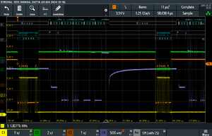
The hubsesnor is build around two PCBs, one that connects to the VESC and the other that sits behind the motor. These boards are build around the atxmega16e5 and communicate with each other though RS422. The bottom board reads out the AS5047 and NTC and sens this data to the top over serial at 1.5 Megabaud. This link is quite fast to be able to send this data at the sample rate of the VESC at around 12kHz. The data and power to the hub sensor are separated with functional isolation to make sure the top electronics are protected from water Ingres and shorts.
Startup and Timing Behavior
The top and hub MCUs share the same flash image so they are easy to update and their protocol is always in sync. During boot the flash of the hub MCU is cleared and it waits for a copy of the top MCU's flash. If this is successful the top green LED will blink every second in three quick bursts. During running this LED should be blinking continuously. If there is no data from the bottom board for 8ms the top board will reboot the hub and send another flash config, blinking of the red LED will occur during.
VESC tool
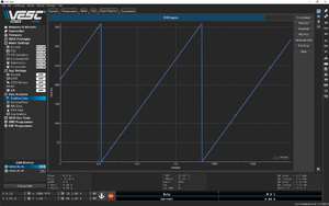
The encoder was tested using VESC tool and a counter value generated at the bottom hub PCB. The data transmission is quite reliable without a motor attached, a spike o0f 360 degrees can be seen every 10 minutes as of git hash "51da04c". DMA on the RX UART could ease the timing requirements on the top board and perhaps reduce this.

