Battery
This page contains the information about the EoI battery development, everything from the requirements to the implementation can be found here.
What is the battery?
The battery is the energy buffer of the boat, it stores the energy coming in from the solar panels and provides a constant voltage for the motor path and peripheral electronics. The battery consists of multiple parts:
- Battery cells
- Battery management system (BMS)
The BMS makes sure that the battery cells can't be overcharged or over-discharged, as this might damage them and present dangerous situations. Besides monitoring the voltage a BMS usually monitors the current and temperature as well.
Technical regulations (as per September 2022)
- Maximum nominal voltage: 58,8V (14S lithium-ion)
- Maximum capacity: 1,5 kWh (= 5400 MJ)
- All battery cells must be commercially available
- The BMS must monitor the battery voltage and current
- The BMS must be capable of shutting down the system
- The BMS must be able to monitor charge and discharge currents
- The BMS must have a means to limit over-current in charge and discharge paths
- The BMS must monitor all individual cells
- All electrical systems must be provided with a fuse in series connection with the main battery ('Main fuse')
- The battery must be fused
- The BMS must be fused
Specifications
| ID | Specifiction | Value | Pass/Fail |
|---|---|---|---|
| Nominal pack voltage | <= 58,8V
|
||
| Maximum capacity | 1,5 kWh
|
||
| Monitor (pack) voltage | |||
| Monitor (pack) current | |||
| Monitor (pack) temperature | >> 1 sensor (8) | ||
| Limit overcurrent in (dis)charge path | |||
| Capable of shutting down the whole system | |||
| CAN-bus communication | 5V / 1 Mbit
|
||
| Internal cell balancing | |||
| Charge and discharge paths can be operated simultaneously | |||
| Motor and MPPT should be enabled independently | |||
| The battery should be enabled with a N.O. contact | open = off
closed = on |
||
| Separate enable contact for Motor path (output) (Optional: Software disable only) | |||
| Battery should be fully disabled (all outputs disabled) by emergency switch | |||
| Shelf life (Save battery mode) | >= 1 year (2.8mA max)
|
||
| Humidity sensor | |||
| Galvanic separation of safety path (bilge and horn) | |||
| (Optional) I.M.U. | |||
| (Optional) Phase change cooling hardware |
| ID | Specification | Value | Pass/Fail |
|---|---|---|---|
| 0 | Motor path (output) | 60V / 300A
|
|
| 1 | Charge path (input) | 60V / 50A
|
|
| 2 | Peri path (output) | 24V / 2.5A
|
|
| 3 | Safety path (output) (bilge and horn) | 24V / 4A
|
| ID | Specification | Value | Pass/Fail |
|---|---|---|---|
| 0 | Ambient operating temperature | 0 - 50 °C | |
| 1 | Ingress protection | IP67 or better |
Battery Management System
The Battery Management System (BMS) is the brains of the battery and makes sure to manage the battery so it is Dedier proof and does not catch on fire.
The BMS has different functionalities on the PCB and therefore different settings. Since these settings are extensive (especially with the Cell Voltage Monitoring (CVM) chip, this chip does more than only measuring the cell voltages but we will be calling it the CVM from now for better readability.
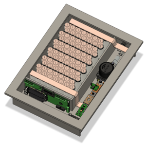
The BMS has different hardware components that is used in the EoI-battery, these are shown in their corresponding figures throughout the page. Shown below is the full battery system with cells in the box.
Hardware
The full BMS system consist of at least three PCBs that are:
- Main board
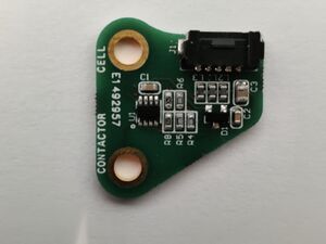
- Current sense board for the discharge
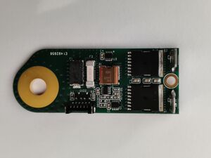
- Charge path board
Each of the hardware are further elaborated in their own sections.
Main board
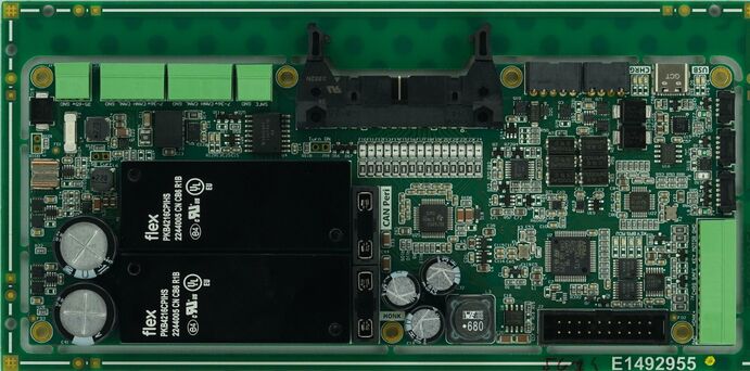
The main board (shown right) is big brain of the battery system. On the main board there are multiple ICs with their own configurations and applications, namely:
- Cell Voltage Measurement IC
- ADC
- Microprocessor
- ...
CVM
The CVM that is used on the BMS is the BQ76952, located in the middle of the main board. This CVM-chip has an extensive list of configurations and features which makes it cumbersome to scroll through the code to know which features are enabled and which safety configurations are made. Therefore a list is generated with a description of the used configuration below.
These are preliminary configurations and could be changed through the course of time and should be changed accordingly here as well.
| Short description | Configuration | Long description |
|---|---|---|
| Min Blow Fuse Voltage | STACK: 60.2V(4.3V per cell) | Permanent faults the device and enables FUSE pin to trigger the fuse.
FUSE pin stays on indefinitely and thus manual intervention is needed. |
| PF_FUSE | Enabled | Whenever a permanent fail occurs the FUSE pin should also be triggered. |
| Internal regualtors 1 & 2 | Disabled | Regulator 1 and 2 are disabled since we do not use that with the CVM on the BMS. |
| Pre-regulator REG0 | Disabled | Pre regulator is used to generate voltages for regulators 1 & 2. |
| CFETOFF | Disabled | CFETOFF pin is not used on the BMS. |
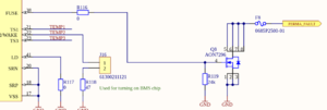
| TS1,2,3 | 18k resistor model & 18k pull-up resistor internal
Used for cell protection |
Temperature pins are configured to be used in cell temperature protection |
| DFETOFF | DFETOFF pin is configured as a termistor input
18k resistor model & 18k pull-up resistor internal Used for cell protection |
DFETOFF can have different functions and is used for temperature measurement as a termistor input. |
| DDSG | Configured as analogue discharge enable | CVM IC can determine if the battery may be discharged. This pin activates the discharge path if everything is within spec |
| DA | Resolution measured current: 0.1mA
Resolution measured voltage: 10mV Internal temperature not used for cell/FET protection |
DA configuration specifies the units for measuring the current and voltage. And can configure if the internal temperature readout should be used for cell protection. |
| VCELL | Disable cell protection on cells 14 and 15 | Configures which cell should be used for cell protection and which cell should be ignored. Cell 14 and 15 are shorted since EoI uses a 14s battery. |
| FET settings | Disabled | The CVM IC can drive its own FETS. |
| FET charge pump | Disabled | N/A EoI |
| Shutdown internal temperature | 80C | If measured internal temperature of the CVM is above 80C than the CVM should go into shutdown mode. |
| Over voltage protection | Over voltage: 4.25V
Delay: 2000ms Over voltage reset: 4.00V |
Over voltage protection triggers alert after Delay resets trigger after reset voltage |
| Under voltage protection | Under voltage: 2.5V
Delay: 2000ms Under voltage reset: 3.00V |
Under voltage protection triggers alert after Delay resets trigger after reset voltage |
| Permanent failure under voltage protection | Under voltage: 2.0V
Delay: 5000ms |
Permanent failure under voltage protection triggers alert after Delay
Needs manual intervention for reset |
| Permanent failure over voltage protection | Over voltage: 4.3V
Delay: 5000ms |
Permanent failure over voltage protection triggers alert after Delay
Needs manual intervention for reset |
| Permanent failure over temperature protection | Temperature: 90C
Delay: 5000ms |
Permanent failure over temperature protection triggers alert after Delay
Needs manual intervention for reset |
| Permanent failure VSSF protection | VSSF: 100mV
Delay: 5000ms |
Permanent failure over VSSF triggers alert after Delay. VSSF is measured internal of the IC.
Needs manual intervention for reset |
| Permanent failure 2LVL protection
EDIT: Should not have to use. |
Delay: 5000ms | Permanent failure over 2LVL triggers alert after Delay. 2LVL is measured internal of the IC.
Needs manual intervention for reset |
| Permanent failure LFOF protection | Delay: 5000ms | Permanent failure over LFO oscillator frequency deviates from expected value after Delay triggers alert. LFOF is measured internal of the IC.
Needs manual intervention for reset |
| Permanent failure HWMX | Delay: 5000ms | Permanent failure for input MUX used for OV, UV protection if check fails and fails after Delay trigger alert.
Needs manual intervention for reset |
| Over temperature protection for charge | Temperature: 60C
Recovery: 55C |
Triggers fail and disables charge path until Recovery |
| Under temperature protection for charge | Temperature: 0C
Recovery: 5C |
Triggers fail and disables charge path until Recovery |
| Over temperature protection for discharge | Temperature: 60C
Recovery: 55C |
Triggers fail and disables discharge path until Recovery |
| Under temperature protection for discharge | Temperature: -40C
Recovery: -35C |
Triggers fail and disables discharge path until Recovery |
| Over temperature protection FET | Temperature: 80C
Recovery: 75C |
Triggers fail and disables discharge path until Recovery |
| Over temperature protection internal | Temperature: 70C
Recovery: 65C |
Triggers fail and disables CVM until Recovery |
| Under temperature protection internal | Temperature: -20C
Recovery: - |
Triggers fail and disables CVM path until Recovery |
| Balancing configuration minimum cell voltage | 3.30V | Minium cell voltage before balancing |
| Balancing cell voltage delta | 10mV | Minimum cell voltage between cell before stopping balancing (or start balancing if bigger than) |
| Number of cells balancing simultaneously | 4 cells | CVM supports multiple cell balancing up to 16 cells. |
Open questions
- Do the MPPTs have to be modified for the 14S battery?
- Integrated or seperate charge/discharge paths? (I've got a slight preference for seperate pcb's)
